The Staples Easy Button is pretty useless by itself. This modification doesn't make it any more useful, but since everyone loves blinky lights, so I decided to add some LEDs to the Easy Button. This project was also the precursor to the Easy Button based Game Show Buzzer System.
Instructions
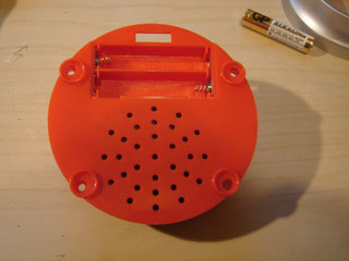
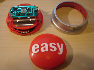
Peel off rubber bumpers and unscrew the screws on the bottom. Disassemble the button.
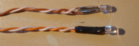
Prepare the 3mm red LEDs by flattening the leads, stripping ~1cm from each of the wires for the LEDs, carefully soldering the LED leads to the wires, and insulating them with a minimal amount of electrical tape.
Hook the LEDs up to power with a current limiting resistor (~100 ohm at 5v for both) to test them.
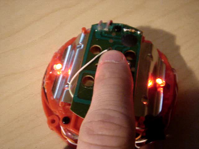
Drill small holes large enough for the LEDs to fit through at the ends of upper red plastic part (see photo below). They should be as close to the edge as possible, away from the big metal piece, diagonally so they point up towards the top center of the button.
Place the LEDs through the holes, place small amounts of hot glue around and in the hole, position the LEDs so the light is as evenly distributed as possible (doesn't have to be perfect yet), check with the button top in place.
Once the LEDs are glued in a suitable place, use a Dremel or even sandpaper to flatten the tops of the LEDs so they are horizontal. Be sure not to damage the LEDs by grinding too much away.
Before proceding with the following steps, ensure the circuit will work correctly by temporarily making the connections and pressing the button.
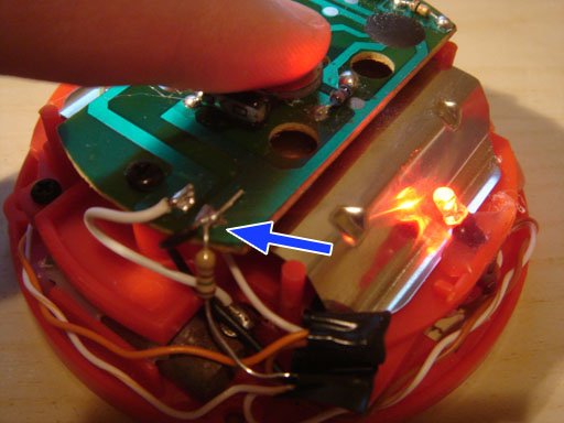
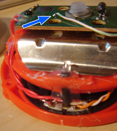
Solder one end of a current limiting resistor to the negative power lead (black) going to the PCB, and the other end to the anode side of the LED (see photo below).
Solder one end of a wire to the spot marked on the PCB below (ensure the voltage at this point is approximately 3 volts when the button is pressed, and 0 volts when inactive), and the other end to the cathode side of the LED.
Repeat for the other side.
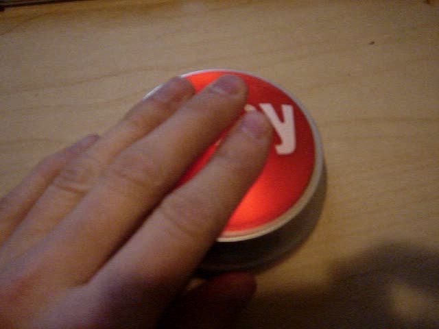
Test the LEDs and button one more time before closing up the casing. Ensure that the button top and silver casing ring are lined up correctly by checking the ridges match up with the grooves.