It's a quiz buzzer lockout system, like the ones they have on game shows like Jeopardy or for high scool and college quiz bowls. Each player has a button to buzz in with, the first person to press their buzzer attempt the question. The purpose of a lockout system is to determine precisely who buzzed in first, so there is no possible debate. In this case, machine is better than man.
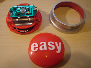
This particular one uses the Staple's Easy Button, a lame marketing gimmick that consists of a large pushbutton that says "that was easy!" when you press it. It also features USB to provide power and connectivity to a computer for integration with quiz software and for firmware upgrades.
Why?
The ACM student chapter at USC was having an engineering themed Jeopardy competition for Engineering Week and needed a lockout systems. Building your own is far cheaper and more fun than buying one, so I figured why not?
And why use Easy Buttons? They're cheap, large, momentary pushbuttons, and easily hackable: perfect for this project.
How?
This project isn't for complete electronics newbies. It's not particularly complex (actually quite simple), but it does involve soldering of wires and programming a microcontroller, which I won't cover the basics of here. Learn to do these things first, then come back here.
The design is very simple. It consists of a microcontroller (I used a PIC), several momentary pushbuttons and LEDs. The buttons are connected to the inputs of the PIC, the LEDs are connected to the outputs of the PIC. The PIC runs a simple loop that reads the input pins and checks for presses of the pushbuttons, and as soon as it detects one is pressed it activates a buzzer for a moment then begins flashing the corresponding LED until it is reset using a reset button.
The hardware and software of the USB portion of the project is a little more complicated, so it's optional. Fortunately the PIC18F4550 series of microcontrollers has USB support so there's no need to deal with the really low level parts of USB.
Parts
Required:
Staples Easy Buttons (minimum two, of course)
Switches (momentary pushbutton for reset)
LEDs (3mm, red, the brighter the better, two per Easy Button)
Resistors (~100 ohm depending on the LEDs and voltage, one per Easy Button; ~10k pullup resistors, depending on microcontroller)
Capacitors (~1uF across microcontroller power supply pins)
Microcontroller (see below)
Power supply (5v, or > 5v with 7805 voltage regulator, or suitable for your microcontroller)
Wire (~22awg)
Cat 5 or similar cable (at least 4 wires, stranded is probably better than solid core)
Breadboard, project box, etc
Optional:
Toggle switch for power
Buzzer (~5V, ~500Hz, miniature)
Optional, but required for USB support:
PIC18F4550 or similar microcontroller
USB connector (Type-B or Mini-B, or just splice a USB cable)
Crystal oscillator (20MHz or another suitable speed)
Capacitors (one 220nF for Vusb, one 100nF to 1uF for Vdd, two suitable for the crystal oscillator, 15pF or 22pF for 20MHz)
Momentary pushbutton switches (one for reset, one to enter boot mode; optional)
See this page for more details on required parts for USB with the PIC18F microcontrollers.
Tools and Miscellaneous Supplies
Microcontroller programmer and software for your microcontroller
Wire cutters and strippers, needle nose pliers, etc
Soldering iron and solder
Hot glue gun and glue
Electric tape
Small phillips screwdriver
Drill and bit set (bits ~1/8", and diameter of chosen cable, ~7/32" for Cat 5)
Optional but useful: Xacto knife, Dremel, hemostats
Preparing the Microcontroller
I used a PIC microcontroller, specifically the PIC18F2455. Most microcontrollers (PICs, AVRs, MSP, whatever) should work but these instructions are for the PIC. Whatever you use, it should have at least 1 input pin and 1 output pin for each Easy Button, plus 1 input pin for a reset button, and possibly 1 output pin for an optional buzzer.
The provided source code was compiled with the MPLAB C18 compiler for the PIC18F2455. If you use it on another microcontroller or compiler you may need to change it substantially. The source is commented with most of relevant details. Several things to note if you are using a different microcontroller:
All inputs and outputs are active-low. This means you set the pin to "0" to activate the LED, buzzer, etc, and when you read the button pins "0" means the button is pressed.
This PIC has internal pullup resistors on PORTB, which is used for the button inputs. If your microcontroller does not have internal pullup resistors on all your button input pins, you will need 10k resistors between each pin and Vdd.
The timing of the buzzer duration and LED blink rate is determined by hardcoded values in the loops. I found my values through trial and error, you will probably have to do the same if your microcontroller runs at a different speed or your compiler generates different instructions.
Preparing the Easy Buttons
Getting the Easy Buttons ready is probably the most labor intensive piece. Each one will probably take at least half an hour.
Take the batteries out. Drilling through batteries is a bad idea.
Peel off rubber bumpers and unscrew the screws on the bottom. Disassemble the button. Replace the silver ring part before drilling.
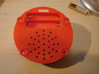
Drill a hole large enough for your cable through the back of the button casing and into the battery compartment. The hole should be slightly above the "crease" in the silver casing, and slightly off mid-line (either side) so you have room for the LED later. You should put the battery cover back on before drilling so it will fit with the cable in place.
Remove the divider from between the two battery sections and the metal battery contacts from the side without the wires. Needle nose pliers work well for both.
Take off the silver casing. Drill another hole on the end of the battery compartment you just removed the battery contacts from.
Replace the silver casing first. Strip ~10cm of the outer sheath from your cable, route the cable from the outside through the silver casing, into the battery compartment, and out the last hole you drilled.
Route one pair of wires to the opposite side for one LED, one pair to the near side for another LED, and a third pair to the top of the circuit board for the button.
Prepare the 3mm red LEDs by flattening the leads, stripping ~1cm from each of the wires for the LEDs, carefully soldering the LED leads to the wires, and insulating them with a minimal amount of electrical tape.
Hook the LEDs up to power with a current limiting resistor (~100 ohm at 5v for both) to test them.
Drill small holes large enough for the LEDs to fit through at the ends of upper red plastic part. They should be as close to the edge as possible, away from the big metal piece, diagonally so they point up towards the top center of the button.
Place the LEDs through the holes, place small amounts of hot glue around and in the hole, position the LEDs so the light is as evenly distributed as possible (doesn't have to be perfect yet), check with the button top in place.
Once the LEDs are glued in a suitable place, use a Dremel or even sandpaper to flatten the tops of the LEDs so they are horizontal. Be sure not to damage the LEDs by grinding too much away.
Solder the button wires to the contacts shown below. Check that these are the right contacts by measuring with a multimeter (resistance should be very high when not pressed, less than about 50 ohms when pressed).
Test the LEDs and button one more time before closing up the casing. Ensure that the button top and silver casing ring are lined up correctly by checking the ridges match up with the grooves.
LEDs have polarity, so you should always be consistent when soldering them to the wires. Pick a color scheme you can remember and stick with it. The buttons don't have any polarity but you should still be consistent.
Putting it All Together
Program the microcontroller and test it before soldering anything. I recommend using a solderless breadboard until you're sure it works.
Connect (either solder or breadboard) all required pullup resistors (the ~10k ones) to input pins if your microcontroller doesn't have internal ones.
Connect one wire of each of the button wires to ground and the other to the corresponding input pin of the microcontroller.
Connect each of the LED anodes (the positive side, usually the longer lead of the LED) wires to Vdd and the cathodes (both negative wires from the same button) to the corresponding output pin of the microcontroller. Make sure it matches the input pin of the button otherwise the lighted LED won't correspond to the pressed button!!!
Connect the buzzer, reset button (along with pullup resistor, if needed), and "ready" LED (along with current limiting resistor.
Miscellaneous Notes
Simple explanation of pullup resistors
When a button is pressed it "pulls" the input pin of the microcontroller to 0V, but when it isn't pushed nothing is normally connected (electrically) to the input pin. A pullup resistor makes that connection to +5V, but the resistance makes it weak enough to still be pulled down to 0V when the button is pressed. The value of the pullup resistor needs to be high enough that ground can still pull it low, 10k is usually a good value.
Simple explanation of current limiting resistors
LEDs have very little resistance when connected in the proper direction, so the current needs to be limited by a separate resistor, otherwise the LED will draw too much current and burn out. Ohms law tells us V = I*R, or more convenient R = V / I, where V is voltage, I is current, and R is resistance. Standard LEDs like about 15mA, we're using about a 5V power supply, so 5V / 0.015A is about 330 Ohms.